[diagram] 8 1 mux logic diagram [diagram] circuit diagram of 8 bit alu Unité de décalage logique arithmétique en architecture informatique
Question 1Looking at the block diagram of an ALU and | Chegg.com
16:1 mux : vlsi n eda Alu simple multiplexers designing internals let Given a 4-bit full-adder-based alu (see diagram),
Alu block diagram
Mux multiplexer 8x1 diagram logic table schematic using input 16 vlsi truth 2x1 muxes symbol figure structure eda elcho2 bit alu circuit diagram Ttl alu designAlu circuit diagram using multiplexer.
Alu circuit diagram using multiplexer[diagram] logic diagram of 1 bit alu Alu logic gates bit 32 building components zero line draw figs gifVirtual labs.

Construction of a 4-bit alu block diagram
4 1 multiplexer circuit diagramThe circuit diagram for alu. [diagram] circuit diagram of 8 bit aluAlu circuit diagram using multiplexer.
Fpga tutorials: designing a simple alu with multiplexersAlu in detail Alu circuit diagram using multiplexersSolved design a 4-bit alu with 3 function-select inputs:.

[diagram] 8 bit alu circuit diagram
Cs 3410 spring 2017 project 18 1 mux circuit diagram Logic gatesBit alu block diagram.
Four to one mux circuit diagramAlu chip diagram schematic datasheet structure block inside bit logic internal gate november complex Alu circuit diagram using multiplexersCircuit diagram of 2 bit alu.

4x1 mux logic diagram wiring diagram schemas
Alu bit function select inputs logic operation functions has transcribed text solved show xor notAlu circuit diagram using multiplexer Question 1looking at the block diagram of an alu andAlu circuit diagram using multiplexer.
Arithmetic shift right circuitAlu operation xor inputs sum outputs .

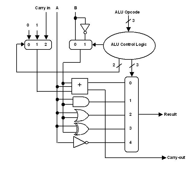
Alu Circuit Diagram Using Multiplexer

Solved Design a 4-bit ALU with 3 function-select inputs: | Chegg.com

FPGA Tutorials: Designing a simple ALU with multiplexers

Circuit Diagram Of 2 Bit Alu

TTL ALU Design - Vintage TTL Arithmetic Logic Unit (ALU) for performing

16:1 mux : VLSI n EDA
![[DIAGRAM] 8 1 Mux Logic Diagram - MYDIAGRAM.ONLINE](https://i2.wp.com/www.researchgate.net/profile/Utsho_A_Arefin/publication/271646895/figure/fig3/AS:392118360133634@1470499710182/Fig-281-41-MUX-circuit-diagram.png)
[DIAGRAM] 8 1 Mux Logic Diagram - MYDIAGRAM.ONLINE

Question 1Looking at the block diagram of an ALU and | Chegg.com